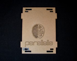
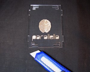
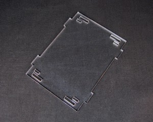
| Step 1: Remove the masking |
| Start in a corner |
 |
|
 |
| and peel off the masking |
 |
|
 |
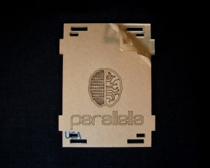
| To remove the masking from the Logo, you can either use a fingernail or an exacto knife. |
 |
|
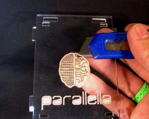 |
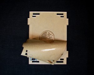
| To remove the masking from the binary section of the logo, simply rub it off with your thumb. |
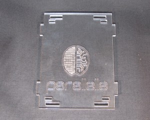 |
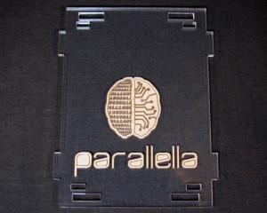
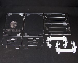
| All the parts should look like this |
 |
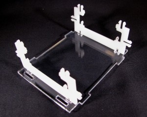
| Step 2: Attach White Mounting Brackets |
| Take the two mounting brackets and snap them into the smaller slots on the bottom panel |
 |
|
 |
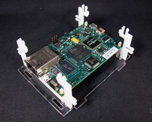
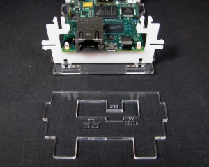
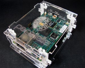
| Step 3: Mount the Parallella Board |
| Slide the Parallella board through the mounting brackets and then push down near the PCB mounting nubs to lock the board in place. |
 |
|
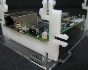 |
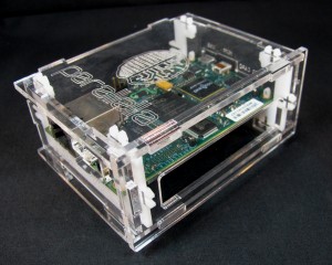
| Step 4: Insert the FacePlates |
| Take the Ethernet/USB/power faceplate and get it in the correct orientation as shown here. |
 |
| Now insert the two tabs into the the slots on the bottom panel at a slight angle to clear the Ethernet port. |
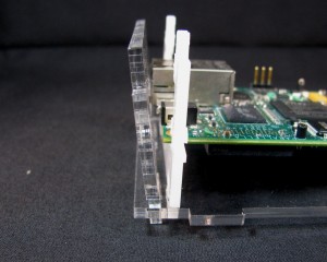 |
| Once clear of the Ethernet port, push the faceplate into a vertical position. |
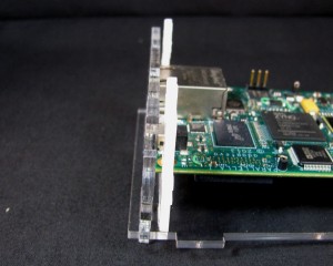 |
| Repeat with the other faceplate. |
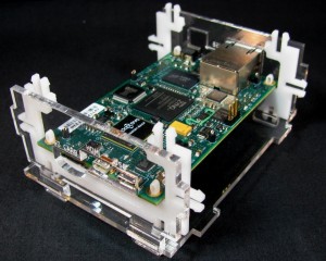 |
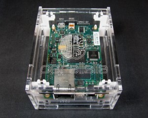
| Step 5: Mount the Top Panel |
| Take the top panel and mount it with the Parallella logo over the Ethernet port. |
 |
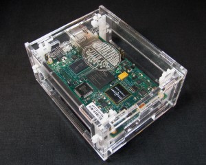
| Step 6: Attach the Side Panels |
| Take the side panels and mount them so that the large slot is vertically centered on the Parallella Board |
 |
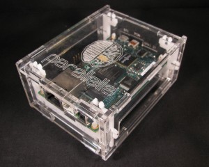
| Congratulations!You have successively assembled your Parallella enclosure. |
 |
|
 |
|
 |
|
 |